


The following article is taken directly from the 1909 edition of Popular Mechanics Shop Notes: Easy Ways To Do Hard Things, pp. 984-986. It should go without saying that I am presenting this only for historical interest, and in no way is this meant to be a how-to guide, or any sort of guide whatsoever. Although the early airships held a good record for safety overall, especially compared to other aircraft of their day, this particular ship would be extremely dangerous if built. The hydrogen gas is explosive, and linseed oil-soaked fabric burns quickly. This is history, not how-to! Enough said.
You may ask, if it was so dangerous, then why would Popular Mechanics print such a crazy article? In 1909 the airship seemed to be the wave of the future. Airplane design was advancing (this was only six years after the Wright brother's first flight), but lighter than air flight seemed at the time to be the more promising and practical method. The world was fascinated by the prospect of powered flight, and many budding inventors attempted to build aircraft. Only a few years later World War I rapidly increased airship design. I am presenting the article here merely as a sample of the sort of elaborate projects the general public enjoyed reading about nearly 100 years ago even if there was no intention of attempting the project. There really isn't enough information here to build a practical airship. Note that the article provides no instructions for piloting the airship!
It should be noted that this article was written by Glenn Hammond Curtiss, who was the premier aircraft and aircraft engine designer of his day.
If you would like to learn more of the history of airships, please visit John Dziadecki's Airship pages.
![]()
The term airship, generally speaking, is applied to dirigible balloons, while the heavier-than-air classes are more commonly
spoken of as flying-machines. The flying-machine, or aeronef,
is divided into three classes: Aeroplanes, which consist of
one or more horizontal planes designed to soar into the air by being propelled forward at an incline; the helicopter, in which the ascensive force is secured by the use of vertical
screws, or propellers; and the orthopter, or wing-beating machine. In this chapter we will endeavor to describe the most simple and practical form of dirigible balloons, while the other types will be taken up in successive issues.
The ascensive power of a dirigible or other balloon is secured by the use of gas contained in a large envelope of oiled fabric or rubber-coated cloth. For the dirigible balloon where the bulk of the gas bag is an important consideration, the use of hydrogen gas, which h as the greatest ascensive power, is desirable; 1,000 cu. ft. of hydrogen gas will lift about 65 lb.
In building an airship, it is well to first determine the weight of the frame, propellers, engine, controlling mechanism and operator; then build, or purchase, the gas hag, of proper dimensions and sufficient capacity to lift the desired weight, together with a reasonable amount of ballast, which in a one-man outfit should be about 50 lb. Experience has taught us that a 7-hp. engine driving a suitable propeller will furnish sufficient pull to drive a one-man airship as fast as it can be readily controlled. Taking this as a basis, let us proceed to enumerate what our requirements and their respective weights will be: An engine of this power in the form of a 2-cylinder air-cooled motor will be the most desirable. This will weigh, with all appurtenances, about 100 lb., the engine alone only weighing 50 lb. From this it will be seen that in securing an engine we must not consider simply the catalog weight of the engine, which seldom includes the ignition system, oil or gasoline tanks, mufflers, etc. Placing the weight of an operator at 175 lb., frame 60 lb., propeller and shaft 40 lb., rudder, drag rope and ballast 100 lb., we have a total weight of 375 lb. Add 80 lb. for the weight of the gas bag and its suspension, and we have 455 lb., which divided by 65 gives us 7,000 cu. ft. of gas required to lift the machine.
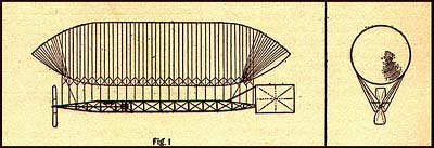 It is apparent that an elongated balloon will pass through the air with much less resistance than a spherical balloon. We will, therefore, adopt a form in which the length is about four times the diameter. A diameter of 15 ft. and a total length of 60 ft. gives us the desired cubic capacity. With this in mind, it is evident that a frame of considerable length must be constructed in order to support this long gas bag for the greater part of its
length. This frame should be 40 ft. in length and can be constructed of spruce in the form of a triangle and properly guyed with wires at a weight of about 1 1/2 lb. per foot. The illustration, Fig. 1,
shows the proper form and method of construction. The frame should be in the form of a triangle measuring about 3 ft. on a side. The length of the spruce sticks would be approximately 16 ft. These sections can then be butted and spliced together by short pieces, lapped on underneath, and fastened by bolting and lashing. Lashing is one of the best ways of making the joint of two or more pieces on an airship.
It is apparent that an elongated balloon will pass through the air with much less resistance than a spherical balloon. We will, therefore, adopt a form in which the length is about four times the diameter. A diameter of 15 ft. and a total length of 60 ft. gives us the desired cubic capacity. With this in mind, it is evident that a frame of considerable length must be constructed in order to support this long gas bag for the greater part of its
length. This frame should be 40 ft. in length and can be constructed of spruce in the form of a triangle and properly guyed with wires at a weight of about 1 1/2 lb. per foot. The illustration, Fig. 1,
shows the proper form and method of construction. The frame should be in the form of a triangle measuring about 3 ft. on a side. The length of the spruce sticks would be approximately 16 ft. These sections can then be butted and spliced together by short pieces, lapped on underneath, and fastened by bolting and lashing. Lashing is one of the best ways of making the joint of two or more pieces on an airship.
The frame is hung underneath the balloon by attaching it to the netting on either side by light-weight linen cords, as shown in the sketch. The longitudinal sticks of the frame should be triangular in form, while the cross sticks should be square.
The engine should be mounted at about one-third the length of the frame from the forward end, and the power transmitted to the propeller shaft by the use of a heavy bicycle or motor-cycle chain. The propeller shaft should be made of 1-1/4-in. 16-gauge tubing, sup-ported by about five bearings and fitted with a thrust for taking the pull of the propeller.
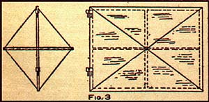
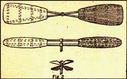 The propeller, Fig. 2, would be 10 ft. in diameter, with an equal pitch. The pitch can be secured by fitting the braces which hold the arms of the propeller to the shaft at an angle of 20 degrees from each other. The arms for the propeller should be made of hickory or ash, and the canvas covering tacked on over light 1/4 in. by 1 1/2-in. slats mortised into these arms. The blade at its widest place should be 2 ft. For convenience in removing or re-placing, in case of accident, the propeller should be made up separately from the shaft and attached to the shaft by two 1/4-in tapered pins. The rudder should contain about 50 sq. ft. of surface and be braced in the manner shown in the sketch. It is preferable to cover this rudder with silk, the wood-work being of bamboo. The rudder, Fig. 3, is controlled by an endless cord running through a pulley in front of the operator, so that he can get hold of it with either hand.
To build the gas bag is perhaps the most difficult part of the construction and requires the most skill. The builder must, after determining the size of his bag, divide it into three sec-tions: the forward taper, the straight cylinder, and the rear taper. The cylinder is composed of straight strips of equal length, while for the tapered ends the silk must be cut in the form of a triangle, with the sides cut on a slight curve. This can be secured by hanging the silk on the wall and attaching silk cord from end to end, marking the silk as the cord hangs. This will give a good form. All of the seams run lengthwise. There is no strain on the silk when inflated in a properly fitting net.
While cotton fabric may be used, silk is by far the better. If properly treated it will last indefinitely. It is much stronger and lighter than other fabric. The first operation in building the balloon is to oil the material. The fabric should be cut in lengths and treated with linseed oil. The oil can best be applied by dipping in a large vessel or tub. The strips should then be hung by one end in a large room, of moderate temperature. This first coat of oil should dry in three or four days, although in some climates it takes considerably longer. After the strips of silk are given one coat of oil and thoroughly dried they may be cut to the proper shape to form the cylinder and cone-shaped ends of the gas bag.
The seams should run lengthwise, and each lap should be double stitched. After all of the silk has been sewed up, a manhole of about 15 in. in diameter should be made in the center, and a small neck, 6 in. in diameter, a little to the rear of the manhole, fitted for inflation. The balloon should then be blown up with air from a centrifugal blower, and a coat of oil put on by brush from the outside. A strip should be oiled the entire length and the balloon rolled over slowly and another strip oiled, etc., until the entire surface is covered. It may then be turned inside out, through the manhole, and the process repeated. After it has been given a sufficient number of coats to make it airtight, powdered soapstone, or French chalk, should be sprinkled over the entire surface inside and out, to prevent sticking. Care must be taken that expansion shall not occur from change of temperature and burst the bag.
The framework is suspended from the balloon by linen cords attached to a square mesh of Irish linen net, as shown in the illustration, Fig. 1.
The net should be carefully adjusted over the bag before filling is commenced. After the balloon is fully inflated, the framework may be placed beneath it and the suspension cords attached, the rudder and propellers fitted on, and the machine is ready for a flight.
Golden Age of the Great Passenger Airships: Graf Zeppelin and Hindenburg
The Great Dirigibles : Their Triumphs and Disasters
Battlebags : British Airships of the First World War an Illustrated History
By Airship to the North Pole : An Archaeology of Human Exploration
Airship: The Home Page for Lighter-Than-Air Craft
This article was printed from the Bizarre Labs website at bizarrelabs.com